Showing posts with label Families. Show all posts

Wednesday, September 4, 2013

Families with Nested Families and MEP Connectors

While trading some emails with Aaron Maller recently he mentioned that he observed that he could create circuits for nested shared electrical families. I don't recall Autodesk publicly taking credit for adding or allowing this behavior but I find that it has been possible as far back as the 2012 release. I'd try earlier releases too but I don't have them installed anymore. Since I started preparing this post I've discussed it with Jose Fandos and he confirmed that it is possible in 2011 too.

I'm a bit frustrated because I thought I tried to explore this possibility a couple years ago while making some electrical content. Rather than dwell on what I thought wasn't possible I'll focus on what IS possible instead.

Experience tells us there are many components that have a variety of options or configurations that can prove difficult to include connectors in, for example a boiler with its electrical panel available either on the right side OR the left side. When a single connector is placed we are inclined to placing it in the "middle" so we can "connect" it to a power supply. That's easier to accept for electrical connections but not as easy for piping or duct.

When the connectors are native, placed directly in a family, it isn't possible to put two connectors in place but disable one or the other. Revit sees both even if we only use one of them in the project. With two connectors in the model we can define where connections take place more accurately but ultimately we end up with one valid connector (connected) and another lurking as "unassigned" within the system browser. It might not a big deal but Revit's developers encourage to assign everything to systems so this approach means there will always be some we can't assign properly.

If the connector is part of a nested shared family and this nested family is assigned a Yes/No parameter to control its Visible parameter we gain control over not only when it is visible but also whether or not Revit sees a valid connector in the host family when it is loaded into a project. This is a crude example with connectors for pipe, electrical and data circuits, offering a conceptual right and left configuration.


When I use a yes/no parameter to control the visibility of the nested families it is interesting to find that the system browser responds to their condition. As can be expected Revit will delete a circuit or system associated with a nested connector if we choose to turn it off.


So far I find that I can create systems, connect pipe and duct, draw wires as well as tag the nested shared families. This means that it may be a bit easier now to define a component that has multiple circuits. This can help counter the limitation that a family can only report circuit information (in a tag) for the primary connector when multiple connectors are in a family.

It isn't perfect...naturally.

Nested families with connectors are harder to see and therefore are harder work with. The connectors are only visible when you hover over the location where they are when you are using the appropriate tool, like duct, pipe or wire. That also means we can't use the convenient right click "create pipe/duct/wire" options because we can't see the connectors.

It may also confront us with a need for sub-categories for connector geometry, not for the connectors themselves but any forms we use to host them. It can be easier to find the connectors if we can see the hosting forms but we may not want to see them in every kind of view.

Ultimately I think it's worth exploring further. Perhaps you'll agree?

Wednesday, June 26, 2013

Type Catalogs and MEP Parameter Syntax

The formatting of type catalog parameters has been consistent until the introduction of Revit MEP features. The WikiHelp at Autodesk provides insight into many things but it still doesn't tackle this subtlety yet. It does offer a number of sample entries, all without a bias toward MEP settings however.

The syntax for Common and Structure data types is parameter name##datatype##units
The syntax for MEP engineering data types is parameter name##discipline_datatype##units

MEP focused examples
Apparent Load##ELECTRICAL_APPARENT_POWER##VOLT_AMPERES
Flow##PIPING_FLOW##LITERS_PER_SECOND
Inlet Radius##PIPE_SIZE##MILLIMETERS
Voltage##ELECTRICAL_POTENTIAL##VOLTS

Structure and Common
MyStructuralParameter##FORCE##KIPS
Assembly Code##OTHER##
bf##LENGTH##FEET

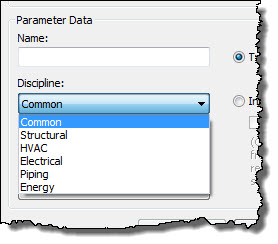
Each MEP related parameter type begins with the discipline it is associated with. In other words when you create the parameter in the family which one of the available disciplines did you choose the parameter from?

If you choose from Common or Structural it isn't necessary to specify them first. It seems to only have been added since the introduction of MEP categories. Another subtle difference is that you'll also find that MEP parameters use the underscore (_) instead of spaces between words in both the data type and the units used.

Examine the Discipline and Type of Parameter wording when you create a new parameter. When you are ready to create your own type catalog headers, refer to those again and as a general rule you can type:
  • Your parameter name
  • ##
  • Discipline
  • _ (underscore)
  • Parameter data type (with underscore between words)
  • ##
  • Units (with underscore between words)
When when I'm not sure what the correct format should be, I either open an existing family or create a new one from scratch that uses the parameter type I'm dealing with. Then I use the relatively new Export > Family Types feature to create a type catalog. If Revit makes it then it must be correct? Right? Better still using that feature can be a shortcut in itself, just clean out the extraneous parameters I don't really want to include in the type catalog. I wrote a post recently offering some advice on Working with Type Catalogs.

Monday, June 24, 2013

Pipe Size Parameter Usage

This is pretty subtle, when you try to add a shared parameter directly to a dimension (even to the "radius" in a connector), ie select "add a parameter" instead of selecting from the list available, it will tell you it has to be a 'length' parameter.


If you load the parameter first using the Family Types dialog as a pipe size you can then select it from the list.

Thursday, June 13, 2013

This Family uses a Type Catalog

A family that has a type catalog must be loaded properly, either with Load Family while placing a component or via Load from Library, or using a right click > reload in the Project Browser.

If you don't select at least one type from a catalog Revit will load the default type, don't do it. Select at least one type to reload or load. Don't drag and drop from Windows Explorer either.

A family that has a type catalog really ought to only have one "default" type. Lately I have settled on using the name: "This family uses a Type Catalog". If I find that type in a project I know it has been loaded at least once improperly. That type will never appear in the project if the catalog is used.

Do NOT use Edit Family (from inside a project) with families that have type catalogs, it puts all the loaded types from the project in the family. If you edit a family that uses a Type Catalog and it has a bunch of types "inside" it either wasn't cleaned up well or someone used Edit Family from a project. Related to this is, do NOT use Load into Project while working on the family, it does not look for or offer the type catalog and you end up with the default type in the project.

An earlier post included most of this but I decided it bears repeating, separately.

Wednesday, June 12, 2013

BlueBryk and Content

I recently spoke with Bruce Madsen. I had the pleasure of sharing a dinner table with him and his wife at RTC in Auckland. One of the things he's struggled with (we've all struggled with) in his work at HOK is finding and keeping up with all the places that we can find content. He's been quietly compiling his own lists and keeping track of this stuff and finally decided it was time to do this in a more formal way, organized and in a way that allows for broader participation.

This is where BlueBryk comes in.


I should take a quick step back and explain that until now Bruce has been working quietly in what he called a private beta. I asked him if he was worried about word leaking out... Since I'm the leak, he's really hoping to get more feedback about what he's built so far, to see how well it fits and meets our needs. I really need to remember to ask him about the inspiration for the name but I'll ignore that for later.

The site is not a place to find and examine a specific cabinet or pipe fitting, at least not at the moment. It is a place to find recommended places to find content. It is a compilation of all the places that he's documented as providing content, not the specific content that is available.

If you visit the BlueBryk site you'll find a clean organized place (a bit of expected blue here and there too). At the very top is a button called "Why Register". That was my first question too, with a cynic's mindset, "Why do I care?". The first reason offered is access to advance searching criteria, which is certainly valid. I think the biggest reason is to give me access to voting on content providers. After all if I really want to make the site work we all need to give feedback into the quality of the content we find. Autodesk's Seek, the more or less obvious "competing" resource, doesn't really deliver on real user rating systems (we can submit feedback), at least not in a "social" way.


After submitting the info as shown above the results are organized alphabetically and the BlueBryk rating appears on the far right.


Links provide access to the websites for each provider, which belong to any one of these categories: Content Exchange, Consolidator, Content Building, Content Store or Manufacturer. In this way the site is a much more elegant delivery of the kind of information my own Revit Inside blog has been doing for companies that use Revit.

The goal of the site is to do a great job of keeping this information current, relevant and reliable...useful. At the moment Bruce reports over 1200 resources are to be found within BlueBryk. If I'm hunting for the perfect supply grill for Revit MEP there are a lot of manufacturers, the question is who provides Revit content? Ideally BlueBryk will make it easier to see which companies or sites provide a matching range of content AND see which ones are highly rated by BlueBryk AND us.

Now that I've mentioned his site, Bruce hopes you'll check it out and help him make it a very valuable resource for all of the Revit (and the broader BIM) community. Have a look for yourself and click the Contact Us button to offer up your thoughts. He's incorporated a blog into the site too so he can provide timely information. Look for him to write posts that help explain what his vision is and where he hopes we will help him take BlueBryk.

Fwiw, another product called Unifi also takes on this problem with at least one big difference, its integration into Revit as an application. BlueBryk is solely a web resource. I don't know if that is a negative or a positive for either but my gut instinct is that not being an app makes it a bit simpler to use it as intended, as a resource, instead of adding yet another thing to manage during deployment for Revit.

Tuesday, June 11, 2013

Family Templates and View Orientation

An exchange of posts at Revitforum.org with Alfredo regarding family templates prompts this post. The thread began with a question about orientation. I've written about this in the past. I was confused by the use of Exterior/Interior labels then.

I find a fair number of new Revit family editors seem to start out with door families. If that's your first foray into content you might starting thinking the top of the view is "front". It's labeled Exterior. I tend to think of the exterior side of a door panel as the front side when making one. This tripped me up for awhile. I wrote the post thinking the other templates were wrong when compared with the door template, at the very least different. Technically they are all the same, front is at the bottom of the page.

I recently examined every imperial family template (release 2014) that is used for 3D geometry. They all respect the notion of orientation where the bottom of the view is front, the top of the view is back, the right side is ride and left is left. Some templates have labels like Exterior/Interior and Placement Side. In the thread at RFO Alfredo noted that the Generic Model Adaptive template does not respect this orientation. In my view it does but when the template was created the front and back views were named incorrectly. The front view is really the back. If we examine geometry using the view cube we'll find every family will show the geometry the same way when we manipulate the cube.

He also mentioned the Profile Mullion template. They've provided labels to help orient yourself when you sketch your profile. In this image you can see that I've created a bullet shaped mullion profile and applied it to a curtain wall. The bullet ends up on the exterior side.


What is curious is that if the profile is not symmetrical the result is a mirrored condition when applied to the mullion in the project. That's a little unexpected.


If, in an elevation view, I place a detail section that looks up the profile matches what I see in the mullion family.


So we have to twist our perspective around a bit to get a sense of orientation. The short story is that mullion profile is a mirror of what we see in plan with respect to right/left orientation. Exterior and interior are displayed as the labels imply.

Definitely quirky...

Thursday, June 6, 2013

Scaling Revit Families

Every now and then there seems to be a convergence in the "Revitverse". A series of events, themes and user attitudes and desires emerges. Lately it seems to be the notion of scaling families. Revit has not permitted the arbitrary "make this 2x bigger" unless we could provide all the constraints and parameters that allow that kind of input and result. For example we don't usually ask for a desk or chair to be twice as large. A chair becomes too big to use if so. I believe that this logic prevailed in their choice to be more restrictive about scaling things as arbitrarily as other software allows.

A common thread in scaling lately has been classical architecture and columns. These are defined by ratios and rules to some extent while the sculpting applied to them seems to have much more freedom. Reading other blogs and attending the Revit Technology Conferences and Autodesk University made me plan to write a post that provides some links to the various places that you can find intriguing information on this subject. With the many bloggers focused on Revit it really didnt come as a surprise that somebody beat me to it. That someone is Mark Cronin, who I chatted with in Auckland at RTC. He wrote a summary of resources that you'll find useful, techniques that capitalize on new features as well as one that recalls a longstanding feature that we've all managed to forget about.

Please let me encourage you to read Mark's post for the details since he took the time to compile it in the first place, you really should.

Thanks Mark!

Thursday, May 23, 2013

Adaptive Point Family and Ramps

Luke wrote a post the other day that shows how to use the "scary" adaptive point family to tag a ramp's slope, since the slope tool doesn't work on ramps.

I used them to identify sloped "ramps" that are really floors for a client last summer. We used a three point family that allowed us to click on a corner of the start of the ramp, then at the midpoint of the end of the ramp and finally at the other corner at the start of the ramp. The resulting triangle is what they wanted to see. Using model lines allowed us to see them in many views without having to resort to placing many annotation families in all sorts of views.


Don't be afraid of the adaptive point family!

Tuesday, May 21, 2013

Revit 2014 Family Template for Two Level Relationships

The collection of Generic Model templates has grown a little bit with this new release, one new template called "Generic Model Two Level Based.rft".


Tuesday, May 14, 2013

Working with Type Catalogs

I recently replied to a question about type catalogs at RevitForum with this stream of consciousness set of comments. I thought it made sense to drop them here too since they mostly work outside of that of context too. I have altered (and added) a bit here and there to make more sense outside the context of that conversation. Here we go:

Many people like to use Excel to edit type catalogs though it is not required to do so and I usually don't bother. You can just edit the information in a text editor, Notepad ++ is a cool free one.

A Type Catalog does not technically need all the parameters that are part of the family, only the ones that vary from type to type. Values that are not in the Type Catalog will be passed on to the family from the default family type. For example you could put height, width and depth in the type catalog only if those are the only values that really change for each type. A type catalog can be quite simple to manage (without involving CSV files) when you only include the necessary values.

The new export family types feature is quite nice to make sure you have the parameters and units properly defined, especially for MEP content. It does not put parameters in a logical order, at least not one that I find satisfying. It also exports all the parameters in the family types dialog and I don't always want them all but it is easy to remove the ones I don't need.

A Type Catalog can include instance parameter values, these are the default value assigned to the parameter, the user can still change them once they are in the project, like any other instance parameter.

If 24 inches is a more useful input value than 2'-0" a type catalog will allow that even if the units in the family or project are assigned to feet and fractional inches. Just change the ##units from Feet to Inches.

Earlier I wrote that Excel is not necessary and that I don't usually use it. I do use Excel (and CSV files) to change column order because that IS a lot easier to do with it. A friend says that we can see the "matrix" when we look at the .txt file, so we don't need Excel. I save the work as a CSV file and then change the extension to .TXT. You have to delete the older txt file first. I don't bother to keep the CSV around. If I need a CSV again I just open the TXT type catalog file directly with Excel and set the delimiter options. Revit only cares about the .TXT file so no point confusing others with a pile of "irrelevant" files in the library folder.

I put the parameters (reorder them) that match the family type name in front of the list (first columns) in the catalog in the order of the naming in the type name, like 600H 800W 150D. So 600,800,150 are the very first values after the type name. I only include values that we want to set during loading and put dimensional values before informational values (text).

Related Family Interaction Advice

A family using a type catalog must be loaded properly, either with Load Family while placing a component or via Load from Library, or using a right click > reload in the Project Browser.

Do not use Edit Family (from inside a project) with families that have type catalogs, it puts all the loaded types from the project in the family. A family that has a type catalog really ought to only have one "default" type. Lately I have settled on using the name: "This family uses a Type Catalog". If I find that type in a project I know it has been loaded at least once improperly. That type will never appear in the project if the catalog is used.

Do not use Load into Project while working on the family, it does not look for or offer the type catalog.

Friday, April 19, 2013

Is it Too Late to Change

Whenever I spend time in the Revit Family Editor I run into past decisions. Sometime they are my own and quite often they belong to somebody else. I've always encouraged people to develop good habits when it comes to using and defining reference planes. I've even been teased about wasting time in a demonstration by naming each reference plane even though doing so wasn't pertinent to the topic. Habits...

I recently encountered a bunch of families that were built by a few people for their project. I was asked to make some changes so a part of the family could be scheduled separately. That meant making use of the concept of making a family "shared". A family that is nested into another is only treated as a symbol when we see it a project. A family that is nested AND Shared is loaded into the project as an actual separate family (appears in the project browser) as well as being visible as part of the host family. This special condition allows for scheduling nested parts as though they are unique parts, apart from the host, as well as permitting us to place them separately. This subject could easily be few separate posts.

While I was digging in I noticed that few if any of the reference planes were named. I also noticed that most of them did not redefine the original reference planes so that they made sense in the context of the family itself. By that I mean that people will use the default Center (Front/Back) or Center (Left/Right) reference planes as a "left" or "right" or "front" or "back" or something...but not rename/redefine them as such. That means that when we examine a family the "center" (the reference plane that Revit thinks is center) of the family is really an edge or side. Autodesk's own content isn't immune to this either.

In this situation I thought like a mechanic, if I've already dropped the transmission I might as well fix some things that I can't get to otherwise, or "while I'm in here"...

Sadly if a project is using this content and people have done things like put hundreds, perhaps thousands, of them in their models, bad things can happen, when they are reloaded. As Mr. Maller says... it can be a "screwtastrophe". Families that have dimensions referencing them in the project will generate the dreaded "dimensions must be deleted" messages as soon as you reload them. Specifically if you change the IsReference status of a reference plane and reload the family Revit can't find the original reference plane anymore. Worse a family might shift its location, particularly if being swapped out for a different version.

I don't think it can be overstated or stressed enough, content needs to be created carefully and good habits need to developed and observed. It may not be too late to make changes but it can be painful.

Tuesday, March 12, 2013

Blends have Two Sketches

From the been there done that department I bring you a little reminder, Solid and Void blends have two sketches; a base and a top. It's pretty common to see two sketches in the base and the user wonders why they can't move on to the top sketch. When the blend process starts Revit is thinking "base", regardless of the orientation of the blend you are making. How can you tell? Easy, there is a button for Edit Top.


That can only be appropriate if Revit thinks we are working on the base. There isn't even a button for Edit Base until after you click Edit Top.


Once you have two complete sketches, each in their own "world" (Base and Top), you can Click the Green Check mark for Finish Edit Mode. If you need to revisit one or both of the sketches you'll find you can go straight to the Base or Top Sketch via separate buttons, just have to select the form first.


Remember, two sketches, two, two are better than one or twice as nice.

Tuesday, February 26, 2013

Voids Voids Voids

If you read through Autodesk documentation for Revit and the best practices document that they published some years ago you'll find casually mentioned recommendations to "avoid voids" because they will negatively impact performance. That turns into a conversation overhead later, "Never ever use voids in families!!" Hmmm...

Recommendations are wonderful, wonderful when they actually mean something meaningful. A warning like don't use more than six voids in a family. That's specific, I better not use more than six voids or something bad will happen to me, and my project. Then again I might just get wild and create families with seven voids just to make other people mad and drive project performance into the gutter?

I've read and heard similar warnings and recommendations for using formulas, "Avoid using too many formulas in your families". Is eight too many or seven hundred? I'm guessing seven hundred is worse but what about twenty five or forty five. Have we crossed into unsanctioned and untenable content now?

I'd love to see more practical recommendations that quantify things better. I seriously doubt a family with several voids is really going to harm a project, even if there are five hundred copies of the family in the project. I suppose we need to turn the Revit "masses" loose and test all kinds of situations to come up with more specific recommendations?

In the meantime I'm going to keep being careful to avoid voids all while wondering how many voids to avoid...

Wednesday, January 30, 2013

Hosted or Not Hosted

The description "hosted" or "not-hosted" that we use for component families can be a bit confusing. Technically ALL families ARE hosted. They are either hosted by a level, a wall, a ceiling, a floor or a face (surface of some element). When we say not-hosted or non-hosted we generally mean that a family is not specifically associated with a certain host element like a wall, ceiling, floor or face. A chair, desk and various other families across many categories are "not-hosted" though truly they ARE hosted by a Level. They can sit on the floor or are free to be above or below it by altering their Offset parameter.

I often think that it is a disservice to spend time calling them just one or the other. It seems more explicit to use a family name that describes what host is required. A family called, "MyCoolFamily-hosted.rfa" might be better called "MyCoolFamily-Face.rfa" or "MyCoolFamily-Wall.rfa" or "MyCoolFamily-Level.rfa". We could reduce it to a single letter designation. For example the families could be named "MyCoolFamily-W.rfa" or "MyCoolFamily-L.rfa". What if the file extension allowed for this subtlety so the names are not affected by it? Extensions for families could be .RFF, .RFW, .RFC, RFF... Uh oh floor and face both are "F"...so we could use S for surface instead of face?

These different placement methods also mean we have to be careful to consider what sort of hosting nature a family has before we start placing it. We have to resort to reading the family name and/or glancing at the ribbon for any placement options to figure out what the family expects us to do. It would be great if a family could be assigned to a primary placement option. For example, light fixtures usually want to attach to a face, not the vertical face option we are offered by default. Ideally we could specify the hosting priority for each family and use the ribbon only to choose an alternative when those rarer situations happen. Maybe the ideal spot for this parameter is in the Family Category and Parameters dialog, like OmniClass and other settings..

Just writing out loud...

Sunday, December 16, 2012

Please Just Say No to 2D Only

If you make a Revit family and it is meant to represent something real, tangible, please don't make it 2D only. In 3D your family doesn't exist and that is usually a bad thing. Everything we put in a building is three dimensional, even wall paper has thickness. If you aren't prepared to model it faithfully in three dimensions, at least use a generic box form that is at least dimensionally consistent with the thing you are representing. If you are documenting clearance zones make it 3d too. You can't use Interference Check meaningfully if it is just lines on the floor.

Resist the temptation to just make it 2D.

Friday, December 7, 2012

Emergency Designation for Families

Electrical panels and light fixtures are just a couple items that often show some shading to make their use for emergency conditions graphically stand apart from the rest. While some shading techniques people use are quite specific (such as shading half or quarters) if an overall shading or color would work you can consider using a Filter instead of editing any families. Here's a screen capture of applying a filter to make an electrical panel look like an "emergency" panel instead of a regular one. Just a thought that popped into my head the other day.

Thursday, December 6, 2012

Upgrading and Reloading Families

I overhead a conversation the other day at Autodesk University. One person suggested to the other that we should always upgrade families to the latest release and then reload them all into our project after it has been upgraded. They theorized that Revit was having to "upgrade" them each time we open a project, like the message we see when a linked file is still based on an earlier version. Assuming that is true they went on to say that upgrading the families and reloading them would avoid this repeated upgrading of content when you open a project.

My gut feeling is that is not true after the project is initially upgraded. I believe that the process of upgrading a project is taking into account the content that is part of the project as well. If I'm correct then the content inside the project is effectively upgraded as well. Saving a family out of the project results in a new family based on that version of Revit too, not the previous one.

Only a developer or product designer/manager could say for certain though.

Friday, October 26, 2012

Pay Content Forward

One aspect of sharing content freely is seeing where things you make turn up. I made a Viewsonic inspired LCD computer monitor years ago and posted it at Revitcity (May 2004 believe it or not!). I routinely see it in models, blog posts, images online etc. Since I made it, it is recognizable to me, but not really distinctively "mine".

It was built with the philosophy of "pretty close is close enough" in mind. No confusion when you see it in a model and few if any challenge it's accuracy or role in a model. It even shows a blue screen and gray "task" bar color when you switch to shaded. Sorry, there is no rendered decal of a Windows desktop, though technically possible. It might be fun to put a Revit 1.0 screen capture on it though?


You may not want to share stuff you make but go ahead share something, not everything necessarily. You may not be able to or your livelihood is derived from selling content. No worries, you'll still get to see your hard work in play. Just get it out there!

Thursday, September 27, 2012

Family Types Dialog - Lock Parameter

This concept showed up a couple releases ago if I recall correctly. I'm referring to this bugger:


The help file says:
    "You can maintain the parametric relationships between labeled dimensions by locking them. To lock a dimension directly in the drawing area, click next to the dimension."
    "When a labeled dimension is locked, all of the associated parameters also lock. This means that as the dimensions are moved in the drawing area, the associated parameters are constrained and the dimension value is preserved."
    "Note: Locked dimensions and their associated parameters cannot be changed in the drawing area. Use the Lock column in the Family Types dialog to change them."
    "When a labeled dimension is unlocked, all of the referenced geometry unlocks and is unconstrained."
    "To lock a labeled dimension from the Family Types dialog
    • Click a dimension in the drawing area.
    • Click Modify | Dimensions tab | Properties panel Family Types.
    • Select Lock to constrain a parameter."
I find that this part isn't true:
    "Note: Locked dimensions and their associated parameters cannot be changed in the drawing area. Use the Lock column in the Family Types dialog to change them."
When I select a dimension string that has been locked I CAN change the value and flex the geometry. What I CAN'T do is drag a reference plane to alter the parameter value "in Canvas". The text is misleading. It sure sounds like I can't alter the parameter at all, except by opening the Family Types dialog.

Another thing that is a bit confusing. In the project environment we can't change the position of elements by selecting a dimension string first and then editing the value. We CAN do that in the family editor. Inconsistent user "feedback" when transitioning to and from. In the project we keep stressing that we must select the element and then edit the dimensions. Exactly the opposite when a parameter is attached to the dimension in the family editor. Uh oh, I just saw a student's head explode...sorry.

    Friday, September 14, 2012

    Invalid References

    Ever see this message?


    There are a number of reasons why it occurs. This is one example that can occur when swapping families. Not all families are created equal. Shocker I know...sorry. When you swap one family for another after applying dimensions you run the risk of confusing the dimensions. Let's take this simple family, GM01.rfa.


    The Right and Left reference planes have corresponding names and IsReference settings. Now lets look at GM02.rfa


    In this family I've made a mistake (on purpose of course), the Right reference plane has a different IsReference setting, it is set to Weak Reference. Technically the family is also a little bit wider than GM01, but that won't matter. If I've added dimensions that reference this family, as soon as I try to swap GM01 for GM02 I get the message I mentioned at the beginning.


    The essence of the warning is that something has changed in a way that Revit can't transfer the dimension reference to the new object. The tricky part is figuring out what that "something" is. Sometimes it is how the family is made.

    [Edit: Btw, I wrote, and scheduled this to post ahead of time, in response to an question via email and a last night I read a post at RevitForum.org that asks why almost the same thing is happening. Serendipity.]