Thursday, September 27, 2012

Family Types Dialog - Lock Parameter

This concept showed up a couple releases ago if I recall correctly. I'm referring to this bugger:


The help file says:
    "You can maintain the parametric relationships between labeled dimensions by locking them. To lock a dimension directly in the drawing area, click next to the dimension."
    "When a labeled dimension is locked, all of the associated parameters also lock. This means that as the dimensions are moved in the drawing area, the associated parameters are constrained and the dimension value is preserved."
    "Note: Locked dimensions and their associated parameters cannot be changed in the drawing area. Use the Lock column in the Family Types dialog to change them."
    "When a labeled dimension is unlocked, all of the referenced geometry unlocks and is unconstrained."
    "To lock a labeled dimension from the Family Types dialog
    • Click a dimension in the drawing area.
    • Click Modify | Dimensions tab | Properties panel Family Types.
    • Select Lock to constrain a parameter."
I find that this part isn't true:
    "Note: Locked dimensions and their associated parameters cannot be changed in the drawing area. Use the Lock column in the Family Types dialog to change them."
When I select a dimension string that has been locked I CAN change the value and flex the geometry. What I CAN'T do is drag a reference plane to alter the parameter value "in Canvas". The text is misleading. It sure sounds like I can't alter the parameter at all, except by opening the Family Types dialog.

Another thing that is a bit confusing. In the project environment we can't change the position of elements by selecting a dimension string first and then editing the value. We CAN do that in the family editor. Inconsistent user "feedback" when transitioning to and from. In the project we keep stressing that we must select the element and then edit the dimensions. Exactly the opposite when a parameter is attached to the dimension in the family editor. Uh oh, I just saw a student's head explode...sorry.

    Wednesday, September 26, 2012

    Column Shading Gets Obstinate

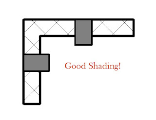
    Working with a client the last couple evenings I found a quirky condition with a column family that has a nested detail component to manage masking the way they like. When the column is playing nicely it looks like this.


    Unfortunately they all, nearly all, look like this now.


    After pressing many buttons, clicking even more and checking, double checking settings...no joy. Then I tried changing the column to use the Column Style settings: Slanted - Angle Driven and Slanted - End Point Driven. They all report Vertical now but changing the value and then changing back made no difference. So I tried placing another column fresh, it works. At least that's something. Then I tried to break it. More button pressing etc. and then I come back to the Column Style settings.


    After changing from Vertical to Slanted - End Point Driven it won't shade/mask anymore. Hmmm... Well I've manage to break it, that's something I suppose.

    I tried to swap all the columns out with a completely new type from a different column family. Then I deleted (purged) the original family and loaded one fresh with a new name even. Swap back...no joy :(

    It sure looks like the only option is to place new columns carefully where the original obstinate ones are thumbing their noses at us. Yuk...

    Fwiw, it isn't actually necessary to include a nested detail component. Usually assigning a solid cut pattern and altering the color to gray is sufficient. These images are actually showing that approach, no nested detail component. That just means the problem is more intractable, not related to the nested component at all. I suspect that the angle column settings "rotate" the "shading" out of plumb and then the columns lose the ability to do it anymore. Much like annotation graphics in lighting fixtures won't show up on sloped ceilings, just the 3D geometry.

    I did find that I could swap out good for bad if I used Groups. I created a group out of one good column, with the group origin at center. Then I made individual groups of the bad columns. I just made sure the origin faced the same direction for each. This wasn't fast... Then I selected all the rogue "groups" and swapped them all for the single good group definition. All fixed...ungroup. ugh

    Tuesday, September 25, 2012

    Only One Book is Allowed

    I wrote a tweet the other day asking,"I wonder why the question, "Which Revit book should I buy?" seems to imply that we are only allowed one, one choice, one on our shelf?"

    We all learn a bit differently, so options are good. I think it is a disservice to all of us to assume one source is sufficient or that we must only pick the "best" book. I learn stuff from all the things I read, even if some parts are useless to me personally or perhaps poorly delivered. We are talking about someone's living. Spending a few hundred dollars in the interest of making a better living seems easy math to me, and I'm not even very good at math!

    Don't restrict your opportunities to learn! My $0.02

    Monday, September 24, 2012

    Who is the Owner

    Melanie wrote a nice post earlier today. She asked:

    Question: What does an owner want from BIM?
    Answer: The same thing they wanted from CAD.

    Which she says begs another question: Who is the Owner?

    It isn't usually a simple answer like: "Let me introduce you to Mr. and Mrs. Smith. We'll be designing their house." They are the owner and you've got to please them, unless they give their kids any say. If so you know which rooms will be the biggest!

    She lists a bunch of people that the software and design industry may overlook too often, or at least focus on others too often, in their quest to satisfy this "owner" person.

    Nice job Melanie!

    Friday, September 21, 2012

    RTC Europe Site and Details are Live Now

    It’s live!! Click the images to visit!


    Following the success of the Revit Technology Conference series in Australasia and North America, industry demand has once again led to us to cross continents! We are very excited to announce that the inaugural European Revit Technology Conference will be held in Delft, the Netherlands on 27 – 28, September 2013. The conference will be presented in English and will showcase a selection of our premier speakers from the Australasia and North America events as well as industry heavyweights within the European market.

    • Experience the benefits you gain from a successful BIM implementation by talking to experts in this field
    • Best of breed invited speakers only, of both European and International origins
    • Share ideas and insights with an international community of your peers
    • Explore the latest trends and technologies
    • Network with your peers
    • Cultivate important business and professional contacts that can benefit your company and your career
    • Come to learn from the experts and leave with a wealth of knowledge, practical methods, and new ideas
    • Unlock the potential of BIM to streamline the building procurement and construction process
    • Overview of new features, Best Practice methods, Tips and tricks from experts

    Thursday, September 20, 2012

    Wednesday, September 19, 2012

    EdgeWise MEP for Revit

    If you use Revit MEP and laser scan data then hopefully you've heard of ClearEdge3D and the new EdgeWise for Revit MEP? They recently announced that they're offering a software solution to bring 3D as-built models of pipes and other cylindrical MEP elements directly into Revit. It automatically extracts pipes, elbows and other features from point clouds and exports them to Revit as fully functional pipe objects. You begin by using their software to analyze point cloud data (the result of conducting laser/lidar scanning on-site). Once processed you can export this interpreted data to several software products including Revit MEP now.

    If you are interested in a demo then check out when Beck Group’s Kelly Cone and Autodesk’s Kyle Bernhardt present it, via webinar, on Wednesday, September 26 at 1pm EDT. Beck Group was one of the early testers of the software and Kelly is quite fond of it. There will be a live demo of it too so you can see for yourself how much time it can save. Click here to sign up.

    I received an email from them recently and I wrote back to ask a couple questions:
      "Is the success of the export and functioning in Revit natively dependent on additional Revit families or based on the what is available in the stock content (US imperial for example)? I ask because I imagine there are elements that can be captured via a laser that your software can understand that might not have an equivalent Revit family element to use. What happens then?"
    Christopher Scotton (President & CEO) responded with this:
      "Thanks for Reaching out. The success of the import is not dependent on additional Revit families because Revit assigns the imported pipe objects to its stock pipe families, in this case Schedule 40 PVC along with the correct type diameter, elbow bend, etc. The centerlines come in as pipe placeholder. However, the accuracy and utility of the model is greatly enhanced by the use of custom families. In essence, EdgeWise imports cylindrical elements that are spatially accurate to the as-built conditions. Once in Revit, the elements need to be changed from the stock pipe family (if not Sch 40 PVC) to the correct pipe family.
      Right now, EdgeWise MEP for Revit only extracts cylindrical features—pipes, round ducting, elbows and conduit—so we’ve not run across many elements that we extract that are not represented by a stock family type. But in those cases, Revit will place a PVC pipe and a placeholder that corresponds to the size, dimension and location of the unrecognized element."


    If you are using point cloud data and Revit MEP (even if you use other software) you should check it out!

    Tuesday, September 18, 2012

    2012 Central States Revit Workshop - Omaha, Nebraska

    If you are within driving distance of Omaha, Nebraska hopefully you've heard about the Central States Revit Workshop? It runs this Friday and Saturday at the Mid-America Center (September 21 & 22, 2012). If you'd like to read their flyer you can download it HERE. Then again for the price (see below) maybe flying in to attend isn't a big deal either!


    This is the schedule/agenda for the two day Revitganza.


    Carla Edwards with Leo A. Daly, among others, has been championing this affair since being inspired by the Revit Technology Conference she attended in Huntington Beach, CA in 2011. Unlike many people who think about doing such things she IS doing it. She and her fellow committee members are doing the hard thing, bringing a Revit workshop to your region.

    The CSRW committee is comprised of:

    Matthew Kuhn, Bill Allen, Nick Meek, Craig Thomas, Barbara Tozser, Carla Edwards, Heath Thompson, Dave Benscoter, Brett Grell, Todd Shackelford, and Casey Eckhard.

    The featured speakers are:

    Paul Aubin, Joe Eichenseer, Zach Kron (a virtual presentation), Shawn C. Zirbes, Brian Johnson, William Spier, Doug Evans, Michelle McCarthy, and Jason Gardner. You can read more about them at the workshop sessions web page.

    Curious how much for two days of Revity goodness?

    $200 For CSI and RUGON Members
    $250 For Non Members

    All registration will be done via Paypal for Conference attendees.

    If you have questions, contact Carla via EMAIL.

    Monday, September 17, 2012

    ecobuild's National BIM Conference Seeking Application Demo Experts

    George Borkovich is looking for people to demonstrate BIM applications at ecobuild's National BIM Conference, December 3-7, 2012.


    THIS LINK will get you to the Ecobuild home page, and THIS ONE will get them directly to The National BIM Conference page.

    He also has a special offer for readers: Register as a LinkedIn colleague and they'll extend a 20% discount off the full conference. All you need to do is go to THIS LINK. When prompted for the discount code, enter the word LINKEDIN. If you only attend the Keynote and Expo, passes are free with pre-registration.

    If you are interested in demonstrating the BIM software you are an expert with then he'd like to hear from you. EMAIL him!

    Friday, September 14, 2012

    Invalid References

    Ever see this message?


    There are a number of reasons why it occurs. This is one example that can occur when swapping families. Not all families are created equal. Shocker I know...sorry. When you swap one family for another after applying dimensions you run the risk of confusing the dimensions. Let's take this simple family, GM01.rfa.


    The Right and Left reference planes have corresponding names and IsReference settings. Now lets look at GM02.rfa


    In this family I've made a mistake (on purpose of course), the Right reference plane has a different IsReference setting, it is set to Weak Reference. Technically the family is also a little bit wider than GM01, but that won't matter. If I've added dimensions that reference this family, as soon as I try to swap GM01 for GM02 I get the message I mentioned at the beginning.


    The essence of the warning is that something has changed in a way that Revit can't transfer the dimension reference to the new object. The tricky part is figuring out what that "something" is. Sometimes it is how the family is made.

    [Edit: Btw, I wrote, and scheduled this to post ahead of time, in response to an question via email and a last night I read a post at RevitForum.org that asks why almost the same thing is happening. Serendipity.]


    Thursday, September 13, 2012

    Working in the Central File

    We are supposed to work in local files. Occasionally people will fire up Revit and end up working in the central file instead. These days it is more deliberate because they have to un-check the Create New Local option to do so.


    Revit has been tweaked over the years to deal with central file editing. I've read claims in a couple books recently that working in a central file prevents other users from using Synchronize with Central (SwC). It isn't true in my experience. If I'm working in a local file I can use SwC as much as I need. The person working in the central file on the other hand will be forced to create a local file when they try to use SwC. They'll get this message.


    I can work in a central file as long as necessary, as long as nobody else is working on the project in local files too. Isolation is fine, collaboration is where the conflict arises. We encounter the message above when a change has been made via a local file while the central file is being edited. While someone is editing the central file a local file user has been able to add or alter an element and then use SwC. When the local file user completes a SwC and the person working in the central file attempts to use SwC the central file editor will get this message (remember Save is disabled in a Central File).

    The message also explains how to resolve the situation, just Save As to save the file with another name, which turns it into a local file. Now SwC will work.

    There are some legitimate reasons to work in the central file, just do it in isolation.

    Wednesday, September 12, 2012

    View Discipline

    Daryl wrote on Monday that the concept of View Discipline isn't documented well. Software documentation tends to be a bit dry, too often a very literal, "Un-checking this turns the feature off". Well that is obvious but "why" would I want to turn it on or off? Unless it is truly self evident, why a feature exists is a bit more involved but much more satisfying help.

    The concept of View Discipline appeared with Revit Structure. It was meant to make it simple to alter the appearance of our model to be more in sync with what a structural engineer wants to see. When MEP (Systems as it was called then) appeared a year later they extended the concept to Mechanical and Electrical (plumbing lumped in with Mechanical till release 2013).

    Daryl used plan views as his example of how the help documentation isn't accurate. Plan views are not the best view type to see the truth in the help claims. Ducts for example, he wrote, don't show up when the architectural discipline is chosen. They CAN show up, they probably won't be visible because they are above the cut plane. When Mechanical is assigned Revit changes the nature of what plan and reflected plan mean. Ducts at 10'-0" AFF will appear in a plan view with the view discipline Mechanical assigned. They won't with Architecture. They are there, just above the view.

    This subtle change occurs because the notion of a plan and reflected plan view means slightly different things to architects and engineers. A reflected plan, architecturally, means that elements that are lower mask elements that are higher, such as a ceiling and light fixtures mask elements above that ceiling. A HVAC plan is different because most engineers want to see the highest duct masking lower ducts. It isn't a reflected plan, it is a plan whose cut plane is, in a way, altered to be above the highest elements and "look down".

    Technically the view range settings can be identical but switching to mechanical discipline will show ducts that weren't there a moment ago when architectural was assigned. They were there but the discipline change altered how Revit calculates the display of the elements. Engineers don't generally do reflected plans so Revit made it easier to generate regular floor plans that show their elements in a way they expect to see them.

    The combination of View Discipline, Object Styles, Visibility/Graphics Overrides and View Range are all responsible for what we see in a given view (technically there are more). Changing one of them is not going to ensure that we see what we really want. We've got to make sure they all have complimentary settings. There is no real difference between Mechanical and Electrical disciplines graphically, based solely on the View Discipline parameter changing. The views dedicated to each of those disciplines also use V/G and possibly view range settings to make them look correct. If you examine the stock templates you'll find that these views have each others element categories turned off (with V/G) to achieve the look we are after. Apart from the automatic graphically biased changes they make, they really just help us segregate views in the project browser.

    In my own way:

    Architectural - All model elements treated "equally", according to Object Styles, but with architectural bias with respect to view range and cutting elements.

    Structural - Similar to architecture but hides non-load bearing walls and some hidden line behavior with respect to concrete floors/slabs and foundations.

    Mechanical - All other disciplines are half-tone and transparent (help says "on top"), duct and pipe and related element categories take priority and behave according to Object Styles. Mechanical elements like duct and pipe will appear in plan regardless of their true elevation with respect to view range, as long as they are within the Primary Range.

    Electrical - Same as Mechanical.

    Plumbing - (new to 2013) Same as mechanical.

    Coordination - Same as Architectural but provides for segregation from it for easier management of views.

    Then there is the Sub-Discipline parameter, a Project Parameter that first showed up in Revit MEP templates. I see architecture firms, that have been exposed to RME, using the same parameter now in their architecture templates because of the added (for consistency as well) control over the Project Browser sorting. That's the essence of the parameter's existence, to manage the Project Browser according to the kinds of views each discipline typically creates. Such as Power and Lighting plans for electrical and HVAC Duct vs HVAC Piping.

    Keep in mind that views in stock project templates are also configured to only show certain element categories according to the discipline bias implied by their name and discipline parameter setting. The combination of the View Discipline parameter and Visibility/Graphic Overrides is responsible (among other possible view properties) for the final result of what you see in a view.

    Tuesday, September 11, 2012

    Shared Parameters aka Dictionary

    A Shared Parameter is like a definition and the Shared Parameter file is like a dictionary.

    Consider that a family parameter is confined to a family. It can be seen from within a project but not scheduled or tagged unless it is a built in parameter like those listed under the Identity group (and provided for us by Autodesk).

    Consider that a Project Parameter is part of a project and applied to categories of families so that it can be scheduled, but NOT tagged. Like a Family parameter it is "trapped" there, in the project.

    A shared parameter bridges both trapped conditions, acting as a definition we look up in a dictionary (the shared parameter file). We store our common definitions there so they can be applied in other projects or families. When you create a family or project parameter using a shared parameter (definition from the dictionary) it is really just another parameter but it has expanded possibilities because it is "shared", the data stored with it can be scheduled AND tagged.

    Monday, September 10, 2012

    RTC Session Datasets for Shared Coordinates

    To the people that attended my session at both RTC events.

    I apologize for being slack!

    It's been months now since Wollongong (May) and only one less since Stone Mountain (June). I'm apologizing because until tonight attendees couldn't actually get the data set files I promised. I've let this issue slip and slide underneath everything else going on and that's not fair. I did try several different times to upload the data but between spotty connections at hotels, the distance and the size of the dataset the upload kept failing. So finally last night we got past that with Bo's help at the BD Group/RTC Events office...thanks Bo!

    Thanks for being patient, even if you gave up on me ;)

    Session Title: Coordinating Projects with Shared Coordinates

    Session in Wollongong, to login for the Materials: CLICK HERE
    Session in Stone Mountain, to login for the Materials: CLICK HERE

    You'll need to refer to the email you received that provided the login password for the conference you attended.

    The only difference between the files offered? There is one project file with "slides" for each location of the conference. The Large and Small project folders contain the same collection regardless of where you attended the session.

    Parameter Related Post Summary

    Updated August 1, 2013

    Posts from 2005

    (2005) What are parameters and why should I care?
    (2005) Sharing Parameters - An Overview
    (2005) Shared Parameters - Part 3
    (2005) Shared Parameters - Part 4
    (2005) Making a Shared Parameter File
    (2005) When is an Instance really a Type?
    (2005) Ignore Good Advice

    Posts from 2006-2008

    (2006) Walking on Thin Ice
    (2007) Family Editor - Parameter Order
    (2008) Duct Size Parameter - Inches - Revit MEP
    (2008) Dept. of Subtle - Filter Parameter in Tags (really subtle)
    (2008) Shared Parameter File - A Little Clarification
    (2008) Shared Parameter - No you Can't -Yes you Can

    Posts from 2009

    (2009) The Order of Parameters - Revisited
    (2009) Titleblock Parameters
    (2009) Which Group? Choosing a Parameter's Parameter
    (2009) Revit Family Style Guide
    (2009) Titleblock Parameters
    (2009) Dept. of Subtle - Family Editor Parameter and Formula
    (2009) Back to Basics: Mark and Type Mark
    (2009) Dept. of Subtle - Three Parameter Tips?
    (2009) Revit API SDK - AutoParameter

    Posts from 2010

    (2010) Export a Shared Parameter
    (2010) BIM Family Toolkit at Autodesk Labs
    (2010) Dept. of Subtle - Parameter Shuffling
    (2010) Family Editor - Use a Default Type
    (2010) Dept. of Subtle - Omni Class Parameters Missing

    Posts from 2011

    (2011) Parameters Again
    (2011) Parameters Again
    (2011) Dept. of Subtle - Family Editor Parameter Lock
    (2011) Dept. of Echo - Type Catalog Formatting
    (2011) Dept. of Echo - Shared Parameters for Manufacturer
    (2011) Family Type Parameter Gotcha
    (2011) Revit Content Standards - ANZRS
    (2011) Dept. of Subtle - Connectors and Diameter
    (2011) No Math Characters in Parameter Names
    (2011) Family Category and Parameter Dialog
    (2011) Shared Parameter Utility - Revit SP Writer

    Posts from 2012

    (2012) Connecting Parameters
    (2012) Connecting Parameters in Nested Families
    (2012) Pushing Parameters Around
    (2012) Parameter Grouping
    (2012) Shared Parameter Article at AEC Bytes
    (2012) The Shared Parameter File has no Relationships
    (2012) A Small Collection of Family Editor Advice
    (2012) Parameter Pecking Order or Priority
    (2012) Shared Parameter Czar
    (2012) Which Overwrite is Right
    (2012) Shared Parameters aka Dictionary

    Posts from 2013

    (2013) Working with Type Catalogs
    (2013) Associate Family Parameter

    Sunday, September 9, 2012

    RTC AUS 2013 - Seeking Abstracts

    Just to further getting the word out the Revit Technology Conference 2013 - Australasia is now accepting abstracts until Wednesday October 31, 2012. CLICK HERE to Submit.


    The abstracts requested, at this time, are ONLY for the conference in Auckland, New Zealand this year, May 16-18, 2013. Separate requests will go out for the other two conferences a little later this year.

    If you want to keep track of RTC information you have options; Naturally the main RTC Site, and I have a page on this site dedicated to RTC, You can follow RTC on Twitter RTCNA - RTCAUS - RTCEUR and RTC on Facebook as well as the RTC Blog and Linked in and Instagram. We're working on a single You Tube channel.

    Have a couple minutes? Considering attending RTC in 2013, then check out this video (00:01:44) to see what RTC is all about. It was created with footage taken from the event in June (Stone Mountain, GA).


    Saturday, September 8, 2012

    Missing Survey Point

    Traded a couple emails with Paul Aubin regarding a client's Survey Point that went missing. It turns out that it had been moved up quite high. I'd never tried to move either the Survey or Project Base Point symbols "up" before so it took me by surprise that it could be done.


    Moral of the story, take care when you are selecting things and moving them. You could move your survey point unintentionally.

    Friday, September 7, 2012

    Connecting Parameters

    You've just downloaded some content from a manufacturer's site and realize that none (or many) of its most interesting parameters are not going to show up in your schedule. This is due to the lack of a common shared dictionary of parameters that we can all rely on. Revit's "system" parameters like Width and Height for some components (like Doors or Windows) just work automatically. Just starting out with a door template means that at least a couple parameters will work without any extra effort. Not true for enough others though.

    The Autodesk Family Style Guide (AFSG) while primarily focused on the needs of Autodesk's Seek site also provides a set of shared parameters we can all use (check out ANZRS too). It's weakness is relevance and timeliness. It has a lot of MEP related parameters but doesn't delve into other disciplines seriously and it's really late to the table. Most of the firms that have been using Revit seriously have already dug into their own shared parameters by now. Redoing their library to be in line with Seek and the AFSG doesn't actually begin to help them unless they really start using a lot of Seek content, which is another can of worms.

    Rather than continuing to lament the situation this post is intended to provide one solution to getting "foreign" content to work within your existing project(s) and template(s). Assuming you've already mapped out your own shared parameter strategy you just need to connect the dots between the parameters the family is using and those that you wish it was referring to, your own.

    It's rather simple really. Add your own Shared Parameter versions of the critical parameters in the family you are working on. For each, in the formula column enter the name of their equivalent parameter. This maps (connects the dots) their parameter value to yours.


    Now you can schedule their component along side your own, even tag if necessary. It's a lot simpler than trying to remap all their parameters to your own by replacing them.

    It is a little risky in that people will have two places that the values could be touched, their parameter and yours. I usually just segregate them in a separate Group. Just let your teams know how you are dealing with content obtained from other sources and it's not mysterious anymore.

    Thursday, September 6, 2012

    In-Place Massing and Project Orientation Inequity

    In-Place families are necessary for some geometry, in particular the massing environment. I've always stressed that people should start a project without being concerned about site alignment immediately. Revit was (is) designed to allow us to adjust True North easily after the fact. As I've written before, just make it easy to "draw on paper".

    A recent post at RevitForum.org underscores that bias when it asked if the two project orientation tools seem to work differently? Actually it was just focused on Rotate Project North (RPN) and that in-place massing didn't play along when it was applied. Rotate True North (RTN) on the other hand does work.

    In this image the massing has been created aligned with the "site" but we've realized that it would be easier to document if Project North were aligned along one building edge.


    In this image I've used the Rotate Project North and picked the reference plane I sketched to mark the East/West bearing I wanted. I had to rotate the text but the tool rotated the reference plane correctly but the massing is unchanged.


    As I wrote in my reply there, RTN is sleight of hand while RPN is really altering the entire model and related views to change orientation. In other words RTN rotates the world under the building and RPN rotates the building on the world. Rotating the world is actually "easier" (less work) for Revit than grabbing every element and everything in every view and rotating it (the building).

    If you heed my Two Pieces of Advice, you'll start a project off better...

    Wednesday, September 5, 2012

    Revit LT

    Autodesk has announced a new version of Revit that they are calling LT. It is the formal repackaging of the Autodesk Labs Project Spark. Users referred to it as a Revit Lite then and it seems Autodesk agreed with the branding.

    When you visit the product site you will see it's being paired up (suite pricing) and compared with AutoCAD LT as well as the obvious comparisons with the full featured Revit. A number of posts and tweets have run down the list of things that it doesn't have. Chief among the features that are missing are worksets, design options, rendering (only through Autodesk 360), no export to IFC, conceptual massing, interference checking, and parts or assemblies. The intended customer is the small firm, small enough that no network licensing either is a detriment.

    I worked for a firm years ago that this product could work for, a small office where each person did their own work for the principal. Sure, there were projects or design considerations that the missing features would prove frustrating but a single seat of full Revit would probably have covered it, collaboration with outside parties that is. I also worked for another guy once that it would fit perfectly but he'd never pay for it. Still using an ancient version of another brand and probably will until retirement. I have also provided support to small firms via my Revit Lifeline that LT could serve well. I can't help but wonder how they'll feel having paid for full Revit with a less expensive option now available?

    It seems unlikely to me that Revit LT will truly serve any notion of BIM other than "lonely BIM". Then again it isn't uncommon to hear people working in the market LT is focused on saying something like, "BIM doesn't matter to what we do." The downside of that perspective is Revit LT may not either.

    [Edit 9/6/2012: I received an email from Autodesk regarding Design Options. Revit LT is intended to include Design Options when it is released. It was not part of Project Spark so that information was carried over into the current press release and web site preparation.]

    Tuesday, September 4, 2012

    Which Overwrite is Right

    When we reload a family a dialog appears asking us how we'd like to deal with the existing family definition. Technically a more involved dialog can also appear if nested and shared families are involved. The first choice or top most button asks if we just want to overwrite the family. The second choice and next button down asks if we want to also overwrite parameter values.


    So what's the difference? The first button is effectively acknowledging the changed family but preserving values that we may have entered or altered in the project, they may be different from the original family. Said another way the project is correct (the project version of the family). The second button is challenging the version of the family in the project, in effect saying, "You are wrong, we'll fix that!"

    I've seen confusion with this result in uncomfortable changes. For example a standard duplex electrical outlet that is set to 180VA is suddenly reporting 360VA. A user changed the default value for a heavy duty type but accidentally assigned it to the standard type too. A reload with "choice two" ends up creating some confusion, replacing the correct values with the new higher value. This kind of change should have been done with the "first choice".

    On the other hand, if the user had changed the type value in the project we could easily fix the mistake with "choice two".

    When reloading families pause long enough to consider the options carefully. Often the best answer (or safest) is the uppermost button.

    Monday, September 3, 2012

    Changing a Username

    Revit stores your username in the Options dialog, Application Menu (the Big R)> Options. Usually this is the same as the username you use to log into your computer. When you enter a different username Revit stores this in the Revit.ini. This stored username is persistent from this point forward. You'll have to manually change it if necessary. Keep in mind that there is a master Revit.ini and a user specific Revit.ini. You can edit them to make sure no username is specified and this will restore the original behavior, using the login username instead.

    That's not the gist of the post though. When Worksets are enabled your username takes on greater significance. There should never be any identical usernames working on a workset project. If there are two Steve's then the first Steve that synchronizes with the central file wins. The other Steve sits in abject misery, quietly imagining how the first Steve will suffer. Don't be the second Steve.

    Still not the point of the post...

    You can change your username before you open a local file but not after. Once Revit identifies you with a file, that files is yours. You can't be someone else and work on that file. You can't change your username until you close that file. Then you can create a new local file after changing the username.

    You can however change your username anytime you want when you work in a central file. It isn't a great idea to actually work this way, switching usernames as you go. It is however a way to clear out users that have not relinquished worksets properly though. When nobody else is working on the project you can open a central file and pretend to be the ill mannered users that haven't relinquished elements properly. It's another reason you might consider working in a central file, even though it is generally frowned upon.

    This is not something you should do casually. If you do this to someone who hasn't saved changes yet, just wasn't ready to do so, you will prevent them from doing so. This won't make you popular at the office. It is an awesome way to resolve little matters when people are all out of the model. In a perfect world you'd never need to do it. Sadly I don't live in a perfect world. If you do, invite me over sometime?