Showing posts with label Ideas. Show all posts

Friday, March 15, 2013

Show Me Wish

Revit offers us the opportunity to "Show" an element when we review warnings, use the Select by ID and fairly often when an error message is generated and we expand the warning.


Choosing Show will often generate a warning that there is no good view to show it in and ask us if we really want to let Revit hunt for a view.


I'd like to be able to specify which kind of views to hunt through before it does its magic. For example I know I want to find a ceiling so don't bother showing me 3D, elevation or section views if I'm really hoping to see just ceiling plan views. Perhaps a new Zoom option: Zoom to Selected that goes to the current element in the view, like Revit will do in a 3D view using the view cube.

Let me help Revit focus on what I'm interested in or think I need. I occasionally have a clue...

Thursday, April 19, 2012

Layer Function Setting

System families have a Function setting. That's true for Walls, Floor, Roofs and Ceilings. I've written about this in the past. Here's what they look like now.


I think the wording of a couple of the functions ought to be revisited, to something like this instead.

Finish 1 [4] = Finish Exterior [4]
Finish 2 [5] = Finish Interior [5]

If changed I suspect people would have less trouble deciding which function is appropriate. I run into wall types quite often that have these wrong or inconsistently applied. If you didn't realize this is how it's meant to work then check out the earlier post.

Saturday, March 31, 2012

Wishlist - Families and Hide at Scales Coarser Than

A casual post at AUGI asked if it is possible to connect a parameter to the Hide at Scales Coarser Than behavior that the annotation for sections and elevations have. This lets us chose a scale (threshold) where the annotation won't display below. It makes it easier to keep certain sections (details/wall sections) and elevations (interior) off of overall floor plan views for example.

Imagine if we could assign this behavior to a family? Nested annotation could be assigned much more effectively because we could design them to only show up at the minimum appropriate scale. Combine this with the Detail Level concept and we'd have even more granular control over the information and geometry in a family.

Related to this is the notion that there are representations that we'd like to control for floor plan orientation and offer a different appear for the reflected ceiling plan (RCP) version. Currently what we show in plan will show the same in the RCP. That's just not specific or granular enough control.

Well, we can keep wishing...and hoping...and wishing...

Friday, February 3, 2012

Oh Where Art Thou Camera?

I wrote a post in March 2008 about this, still waiting. It would be excellent if in plan we could document where a camera is placed. Sure we can create a family to document where they are but that doesn't provide the automatic view reference that other view annotation enjoys. Seems kind of un-Revity to me, you?

If you decide to create a camera annotation how do you know exactly where it is after you place the camera? Good old "right click" will help, just select the view in the Project Browser, Right Click and choose Show Camera. Make a note of where it is and drop your annotation there.

Tuesday, December 20, 2011

Bending Railings to Your Will

Food for thought, what if we used railings for millwork and egress paths? By millwork I mean custom work, not fixed sized cabinets which are often referred to as casework by some architecture and interior firms). As for egress paths, I've written about them many times (I've put a list of those posts at the end of this one) in the past and the example of using a line based family kept me busy for quite some time with requests from people to get their own copy. Busy enough that I finally made it possible to download directly without needing to ask. I also recently mentioned the technique that Brian Mackey uses to demonstrate stair clearance using a railing, so that's yet another way to bend railings to your will.

A railing can do the same task as the egress path I've written about. That example only came about as a possible example of how to use the new line based family template (new in 2006), not something optimized for the task but it's worked pretty well over the years. If you consider applying a "person" profile to a railing, like for Brian's stair clearance, you've just got to sketch the path the railing takes. You can schedule the railing and provide a similar tagging approach to identify each path as different as well as display the total length. Give it a go?

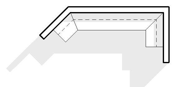
Back to the idea of millwork. Railings are based on profiles, so are cabinets, at least when you are being really schematic. Obviously it won't really do the job for fabrication or construction documentation. If you want a fast way to "draw" millwork a railing works pretty well. A railing sketch is really tolerant of the path being straight or curved too. To get started you sketch the base cabinet profile, save it. Sketch the upper cabinet, save it. You can incorporate the counter profile in the base or make it separate. Load the profiles into a railing type and adjust some values and you can get something like this.


It works pretty well as long as you don't care about seeing drawers and doors. What you see in the image above is railings posing as millwork cabinets and face-based families (line work only) assigned to the Casework category.


It is necessary to keep the upper and lower cabinets separate otherwise you can't get them (upper cabinets) to show up above. In the plan view you see here I've temporarily turned on the underlay so I can apply the Linework tool to see the upper cabinet. Relatively small price to pay for the views that really need to see it.

The neat thing about this approach is that you can get schematic design info such as overall length of different millwork conditions via a schedule. Then when you are ready to dive deeper you can replace them or, as in the image, overlay face-based families to "finish" the detailing. One schedule (early) for schematic and  another (later) for a more detailed summary of cabinets pieces and parts. It isn't hard to make a railing look a lot like something else in a schedule. Just change the schedule title, rename the railing type, change the assembly code values and you've got a pretty convincing railing slash millwork. Maybe call it milling or railwork?

It won't satisfy everyone or maybe anyone...well it did make a few folks more content than they were a few years ago when we decided to do it.

Past Egress Posts (a summary)
Egress Path
Egress Path Update
Egress Path Tags - New Versions
Egress Path of Travel Uh Oh
Egress Example Update
Egress Regress
Egress Family Arc Version

Wednesday, August 31, 2011

In Search of a Side Door Managing Links

I wrote about the Manage Links dialog yesterday. Something else has been bugging me about it so here's another post. I'd love a side door to Import a file from the Manage Links dialog!!! It would be nice to be able to click Import File when I've realized that I need to do that instead of closing the dialog and then clicking the front door buttons for the task. Each tab could have its own side door for the appropriate file type. Crazy?


There are other precedents like the Materials browse button in the Edit Assembly dialog for walls, floors, roofs, ceilings. Another precedent, the browse button for accessing Assembly Code data?


See, not so crazy me thinks!!