Showing posts with label Railings. Show all posts

Wednesday, August 29, 2012

Railing as Egress Paths

I've written about this before, egress stuff seems to be popular at times. A railing is a path and profile based element is easy to sketch something like the path to an exit. Straight and arc segments as well as even sloping conditions. Some of the other methods that I've written about here have the advantage that they can document the total length easily. A railing schedule will report the total length but we can't tag them with their total length.

Case-Apps to the rescue!

They've written a little application that is part of their larger suite of free, subscription and beta software for Revit. It's called "Send Railing Length to Selected Parameter".


Create a shared parameter called "Egress Path", add it to your project and assign it to the railing category. Sketch your railings disguised as egress paths. Now tag them. Oh right you can't show that value. Edit the tag family to create your own and use the same shared parameter. Reload the family and still nothing. Now use the Case app. It will let you select the parameter to use and plug the total length into each railing and that value will appear in your tags!

It's not automatic or fool proof. But it does make it a lot easier to consider a railing. If you like special graphics at the beginning and end of your egress paths then a railing is a bit fussier because you need some special "balusters" to get unique "symbols" at each end. Not impossible just a bit more work. Not necessarily more or less work than the other techniques, pick your poison!

While you are at it you should consider the rest of the pile of apps they have. You'll get their apps manager application which really makes it pretty easy to get and install them. I had both 2012 and 2013 installed in a few minutes after registering.

Thanks Case-inc guys! (wearing my T-Shirt as I write this, they gave me a shirt at RTC in Stone Mtn. in the interest of full disclosure)

Monday, January 23, 2012

Color Fill Legends Mixing with Stairs and Railings

David Light wrote a post about getting stairs to display better when color fill legends are involved. Then Brian Mackey wrote a post to offer another solution. David's approach involves using a solid fill and matching color to "blend" the color fill and the solid fill colors. Brian's involves using the new "Ghost Surfaces" feature.

To offer my two cents I wrote a comment to David's post after reading his. I mentioned what happens when we use the "Transparent" option for categories in Visibility/Graphics or using Override Graphics in View feature > By Element.

This is what you see on screen (using the "Transparent" option to "Override Graphics in View > By Element")(uh oh):


And this is what you get when you print (oh? okay):


Intrigued because I didn't bother to try the approach Brian suggested, I tried it. Using the "Ghost Surfaces" option to "Override Graphics in View > By Element" you see this on screen (looking good):


This is what you get when you print (oh, not so good):


Tag...you guys are "it"! :)

Friday, January 6, 2012

Hacking at Railings Again for 3D Grids

An exchange at RevitForum.org discussing 3D grids for 3D views or exporting to Navisworks prompted yet another "hackalicious" thought for Railings. I posted a VIDEO or this video so you can see and hear me discuss the concept. If you want to cut to the chase you can download the example project file (just scroll to the railing section on the page).

Aaron Maller shared some images (in the RFO thread) and concepts behind the line based families they've been using. Seeing them and reading the other posts made me think of railings yet again, because they don't mind curved paths and multiple segments. That and I'm not good with math that involves letters, weird signs or code.

    By the way, several Dallas area based RFO members (Dan, Jose, Bob, Tanner, Aaron and me) got together for dinner last night and I mentioned it to Aaron so naturally I ended up writing this post tonight. We went to Taverna by Lombardi. Dan found it because I mentioned I was in the mood for risotto (yum!). Thanks to Dan for getting it organized! Sorry, I digress...

The first thing I did was create a baluster family to show a grid name, using 3D Text. Then I created a profile for the "railing", just a thin rectangle "kick plate" to "trip" over in the model. Once they were loaded into the project I created a new type for each Grid name, you'd need a type for every grid name in the project.


With the the types established I'm ready for railing types. I just created a new railing type for each grid as well. Then it's click click click... adding the matching baluster type to the railing type. Yep, this is the tedious part. It's more fun once you get to sketch the grids...define "fun" though?


Like I said railings don't mind curves so here's a curved grid added in.


Last image is using "nicer" grid stands to identify them, more like the example Aaron showed at RFO.


Listen and Watch my video here?


In actual use, I'd start in a empty project file and link in the project file that has the governing grids in them. Then use Copy/Monitor to create equivalent Revit grids and put the 3D grids (hacked railings) on top, at each level of the bldg. Copy/Monitor let's me open my 3D grid file any time and see if there are any changes I need to be aware of. I just have to provide a new export to .nwc (or .dwg) any time there is a change, and pass along the new file.

Thursday, December 22, 2011

You've Got a Bad Profile

Considering the time of year and checking lists you don't want a bad profile. If you create a profile family for a railing and don't do a very good job of it Revit won't offer you your profile in the list of available profiles.


The missing profile you expect to find here is a clue that your profile is bad. You need to check your sketch to  make sure you don't have a Bad Sketch. Only kids with a good profile get to use their profile in their railings.

Tuesday, December 20, 2011

Bending Railings to Your Will

Food for thought, what if we used railings for millwork and egress paths? By millwork I mean custom work, not fixed sized cabinets which are often referred to as casework by some architecture and interior firms). As for egress paths, I've written about them many times (I've put a list of those posts at the end of this one) in the past and the example of using a line based family kept me busy for quite some time with requests from people to get their own copy. Busy enough that I finally made it possible to download directly without needing to ask. I also recently mentioned the technique that Brian Mackey uses to demonstrate stair clearance using a railing, so that's yet another way to bend railings to your will.

A railing can do the same task as the egress path I've written about. That example only came about as a possible example of how to use the new line based family template (new in 2006), not something optimized for the task but it's worked pretty well over the years. If you consider applying a "person" profile to a railing, like for Brian's stair clearance, you've just got to sketch the path the railing takes. You can schedule the railing and provide a similar tagging approach to identify each path as different as well as display the total length. Give it a go?

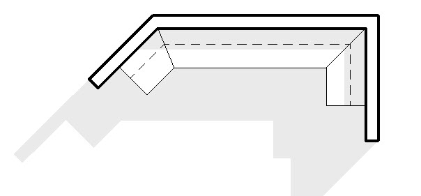
Back to the idea of millwork. Railings are based on profiles, so are cabinets, at least when you are being really schematic. Obviously it won't really do the job for fabrication or construction documentation. If you want a fast way to "draw" millwork a railing works pretty well. A railing sketch is really tolerant of the path being straight or curved too. To get started you sketch the base cabinet profile, save it. Sketch the upper cabinet, save it. You can incorporate the counter profile in the base or make it separate. Load the profiles into a railing type and adjust some values and you can get something like this.


It works pretty well as long as you don't care about seeing drawers and doors. What you see in the image above is railings posing as millwork cabinets and face-based families (line work only) assigned to the Casework category.


It is necessary to keep the upper and lower cabinets separate otherwise you can't get them (upper cabinets) to show up above. In the plan view you see here I've temporarily turned on the underlay so I can apply the Linework tool to see the upper cabinet. Relatively small price to pay for the views that really need to see it.

The neat thing about this approach is that you can get schematic design info such as overall length of different millwork conditions via a schedule. Then when you are ready to dive deeper you can replace them or, as in the image, overlay face-based families to "finish" the detailing. One schedule (early) for schematic and  another (later) for a more detailed summary of cabinets pieces and parts. It isn't hard to make a railing look a lot like something else in a schedule. Just change the schedule title, rename the railing type, change the assembly code values and you've got a pretty convincing railing slash millwork. Maybe call it milling or railwork?

It won't satisfy everyone or maybe anyone...well it did make a few folks more content than they were a few years ago when we decided to do it.

Past Egress Posts (a summary)
Egress Path
Egress Path Update
Egress Path Tags - New Versions
Egress Path of Travel Uh Oh
Egress Example Update
Egress Regress
Egress Family Arc Version